
Importing bend and cell components
This document explains how to include various components like bending aids, STOPA carts etc into Flux.
Bending aids
Bending aids provide assistance for operators especially for heavy or large parts. There are bending aids for the TruBend 5000 and 8000 series, which are mounted on the front side of the press table on guide rails so that they can be shifted to the left or right and can be used in addition to the supports as shown below.
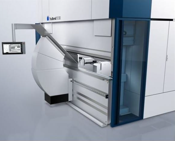
The bending aids can be flexibly adjusted and programmed (height, adjustment of the die width, speeds, position). The bending aid can be moved in Z-Axes only manually.
This section explains how to add new bending aids into Flux.
-
Usually, three mesh files will be given for bending aids namely plate.mesh, carriage.mesh and table.mesh.
-
Create a new folder with the bending aid name (E.g., TB8000_2000N_B36) in X:\Wad\core\bend\bendaids.
-
The given mesh files must be placed in X:\Wad\core\bend\bendaids\<New bend aid name>. E.g, X:\Wad\core\bend\bendaids\TB8000_2000N_B36.
-
After placing the mesh files in the corresponding folder, copy bendaid.curl and mechanism.curl to the same folder, from an existing bending aid that has similar kinematic and parameters. An example of mechanism file can be seen below.
(Mechanism){
  Name:BAID_TB8000_2000N_B36  Children:[
    { Name:Carriage  Joint:Translate  JVector:1,0,0  JMin:-1000  JMax:1000  JasDrawn:0  Color:White
      Geometry:(FileGeometry){ File:Carriage.mesh  Shift:0,0,100 }
      Children:[
        { Name:Table  Joint:Translate  JVector:0,0,1  JMin:50  JMax:200  JAsDrawn:0  Color:White
          Geometry:(FileGeometry){ File:Table.mesh  Shift:0,0,0 }
          Sockets:< Hinge=0,0,0 >
          Children:[
            { Name:Plate  ConnectTo:Hinge  Joint:Rotate  JVector:-1,0,0  JMax:56  Color:"#4A4A4A"
              Geometry:(FileGeometry){ File:Plate.mesh  Shift:0,0,0 }
            }
          ]
        }
      ]
    }
  ]
}
Edit the Name to include the correct name of the bending aid.
-
Similarly make changes to the bendaid.curl file. An example of it is shown below
(BendAidDef){
  Kind:TB8000_2000N_B36  DieV:"16:250"  DieHeight:"-30:250"  MaxAngle:55  Payload:300  Speed:45
  Table:"-159,-1032:159,-245.6"  XExtent:"-213:213" CanChangeForwardSpeed:False
  CanStopAtReturn:True  AdvancedControl:True
}
Edit the Kind to include the correct name of the bending aid.
-
Now we have to change XExtent and Table fields in the bendaid.curl as per the given mesh files.
-
XExtent is the X-Span of the bend-aid (when positioned at 0) which can be measured as shown below:
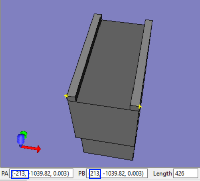
As per the measurements set XExtent field as XExtent:"-213:213"
Note: If you find measuring mesh files difficult, request original SAT / IGS files and measure using MetaCAM.
-
Table is the bound of the support table in top view.
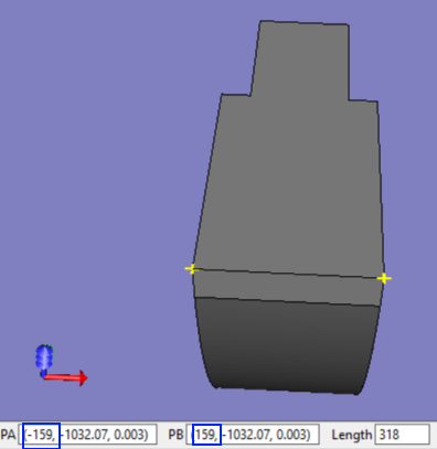
Above image shows the bound in X.
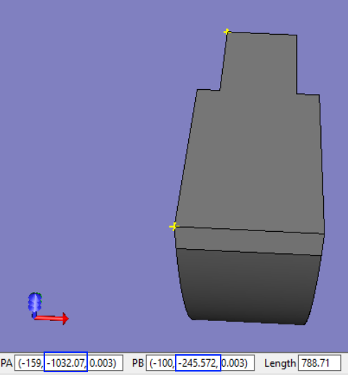
Above image shows the bound in Y.
As per the measurements set Table field as Table:"-159,-1032:159,-245.6"
-
Once the above steps are completed, add the new kind in BendAidDef in the code and make changes so that it appears for the respective machines for e.g. only for B36 machines or B31 machines.
-
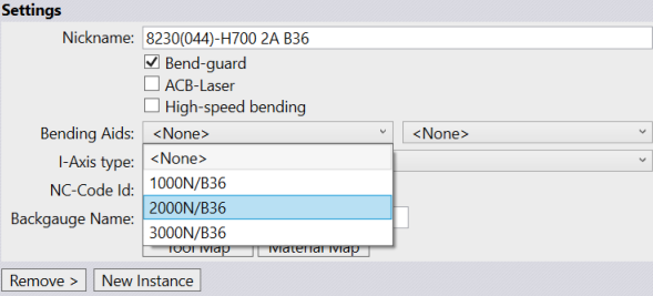
Check if the bending aids are listed in Flux for the respective machines in machine database as shown below:
-
Set the bending aids for a machine and tool a part with that machine and check if the bending aids are engaged properly.
-
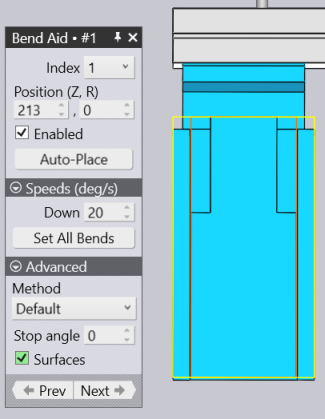
Check if the bending aid surfaces are shown correctly using the the Surfaces checkbox available in bend aid glob as shown below.
-
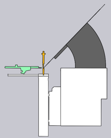
Also, see if the carriage appears connected properly with the die rail in the side view as shown below:
-
Finally, commit the changes (mesh, curl etc) to the Flux repository.
STOPA carts
STOPA carts are pallets which can be included as a cell component for pickup and deposits. Though pallets can be imported in Flux directly, there are some pallets which are included in Flux by default. This section explains how to include a STOPA cart as a default cell component in Flux.
Usually, 3D models of STOPA carts are given.
-
Cleanup the 3D model using MetaCAM.
-
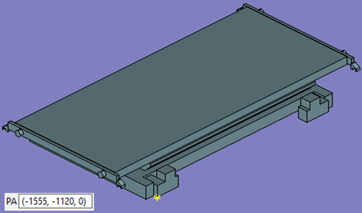
Make sure the origin of the model lies in the center and that the Z height in the left-most bottom corner is 0. The Z height should be 0, as the height of the pallet will be calculated in Flux based on this. See picture below.
-
The crash model must be created, which can be a simple rectangular box model as shown below
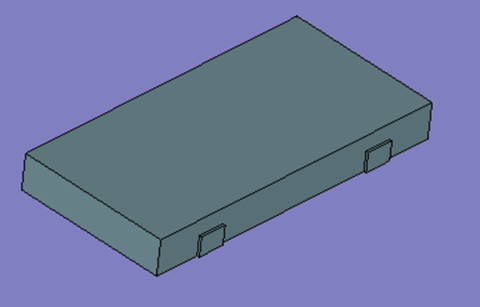
-
Create a new folder with the size of the STOPA as name (E.g., 4200.1800) in Y:\Models\BendCell\Pallets\STOPA. Name the models as Model.3d and Crash.3d and place them in the newly created folder.
-
Use Flux.Console Convert3D with option Extralow to create the mesh files.
-
The mesh files will have to be placed in X:\Data\Archive\CellItems\<STOPA ID> folder. Open the manifest file in X:\Data\Archive\CellItems and pick the next available ID for the cell component you are adding. If we are adding a pallet, the next ID will be 2027. There are gaps in IDs in the manifest to accommodate different types of cell items.
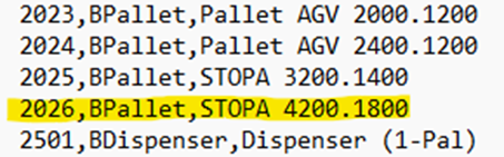
In the manifest.txt, add an entry with the ID, Type and Name of the component as highlighted in the image above. The name should follow a standard convention which includes the type of pallet and the size (E.g., STOPA 4200.1800).
-
After placing the mesh files in the corresponding folder, copy item.curl and mechanism.curl from an existing cell component of the same type. An example of mechanism file can be seen below.

Edit the Name to include the correct ID of the component.
-
Similarly make changes to the item.curl file. An example of item.curl is shown below

See point 6 for the ID and Name conventions. The Size is the size of the pallet as mentioned in the model. The FloorHeight is the height of the pallet from the ground. The Floor attribute represents the diagonal co-ordinates of the pallet’s top plane. See image below for reference.
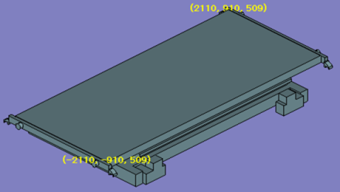
-
Once the above steps are completed, you can check whether the new cell components are being listed in Flux when trying to add Cell Component.
-
Commit the 3D models to Reflux repository and the cell component files (mesh, curl and manifest) to the Flux repository.