Importing bend machines
Usually zip file with bmachine.ini and .3d models with some pngs for decals will be given as machine data. These files may require some changes and cleanup.
Here is a checklist to be verified while importing bend machines into Flux.
-
A new Version field has been included to facilitate the Clamp definition refinement. Refer this case. Version field must be set to 1 in the MacData section in order to import bend machines. BMachine INI files without Version or Version set to zero will not be imported.
-
ID field must be set for the machine.
-
ID is based on the OEM, tech type and running sequence within that OEM/Type. For eg if ID=2420001 then 24 = Ermakson OEM ID 20 = Press-brake 001 = Sequence within this OEM/Type
-
In general, you can look through the machine manifest.txt, and pick the next available ID within that OEM. Take the largest ID within that OEM and add one, don’t use any 'gaps' even if they are there (they are usually machines we have deleted).
-
If it is a new OEM, the code can be assigned by this procedure:
-
Check out the list of manufacturer codes in this DevBook page: https://metamation-devbook.onrender.com/technotes/machineids.html
-
Pick the next available one and use it
-
Update the source of the above machineids page to include the newly added OEM code (you can find it in the DevBook source Bento site: https://github.com/metamation/DevBook)
-
-
-
Old bmachine.ini files will have Manufacturer, this must be changed to Brand.
-
Wibu field must be set in bmachine.ini, if the machine requires a WIBU license. Only then will the EPost attribute be created in machine.curl. Without this, the machine will not be properly installed in TecZoneBend. Refer this case.
DevNotes:
If the Wibu field is set, say for eg if the Wibu field value is TRUBEND_8230_B6, then check if the Wibu code exists for it in Flux. It should be found in Permit.cs file in EPost enum and in sPosts array of TWibuLockBoost and TWibuLockTrumpf classes.
-
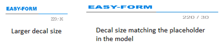
Match the decal image size to the size set in the machine model. If the image is larger than the place holder in the model, then the image will not be rendered properly (see picture below). Refer this case for more details.
-
Name and NCName of the machine in the machine.curl should use the format as seen below.
-
Name: 8600 (044)-H700/HD 6A B36NC Name: TruBend 8600 (044) H700/HD (6-axes) B36 -
Name: ProBend-Smart-1730 2ANC Name: ProBend Smart 1730 (2-axes)
-
-
Sometimes user will provide tonnage value in tons, but the tonnage should be in KN.
For eg, if the given value is
110Tthen it should be set to1100in bmachine.ini.[MacData] ID=2220022 Brand=Proteck OpenHeight=500 TableLength=3200 Tonnage=1100 -
Old bmachine.ini files will have [ClampInfo] section which must be changed to [Clamp] section. If the same clamp model is used but with ram at different height, then a shift must be applied to the ram model. Refer this case. The clamp definition must not include the Open Height in Shift, as all clamps are by default raised to that height. Refer this case.
-
Make sure every model has minimum number of surfaces and layers. Because unnecessary layers will create unnecessary mesh data into Flux. Check the Layer conventions for more information.
-
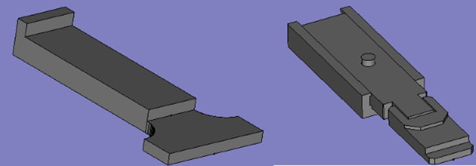
If the machine has flat bgs, in other words if both bg models are same only one .3d file can be used which will reduce the unnecessary bg2.mesh. Below image shows a couple of flat bg models.
-
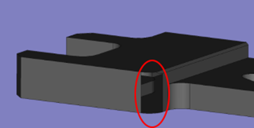
Make sure if all the surfaces look correctly. For eg: The below image shows that a surface is missing.
-
Refer this case to import machine using FXCMD.
Edit the bmachine.ini file and change the machine ID to the range 1000 … 1999 before importing. Only that range is supported, and these machines become test machines.
To import the machine create an FXCMD like this:
[Header]
Type=FluxCommandFile

[Command]
Type=ImportBendMC
InputFolder=W:\BMC\1001
Note that Flux will automatically create the machine in {Data}/Machine/{N} folder, where {Data} is your Flux data folder and {N} is the machine ID. If this folder already exists, the command will fail (to avoid overwriting data, so delete that folder before running this).
DevNotes:
Use Flux.Migrate.exe ImportBendMC <InputFolder> to import the machine. This will create machine folders in X:\Data\Machine.
-
After importing make sure you turn on everything in display and verify if the layers in the machine have come properly.
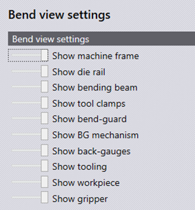
-
For example in the below image, cylinders are missing and the beam is hanging which has to be rectified.
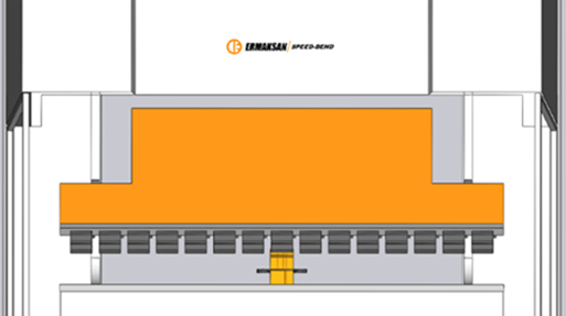
-
Make sure the punch valency and die valency are correct. Below image shows that there is some discrepancy in punch valency and the clamp style
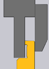
-
Sometimes, the clamp origin may be wrong, and the punch will not be in proper place as shown below. In this case the origin needs to be modified properly.
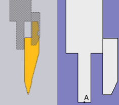
-
Flip the punch and check if the punch is held properly by clamps.
-
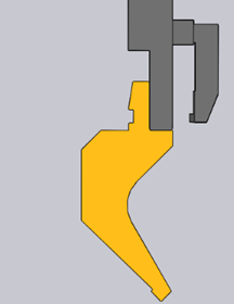
In some cases, the flag DontAutoFlipTool needs to be set. For eg, single clamp style as shown below will have punch hanging if this flag is not set to 1.
-
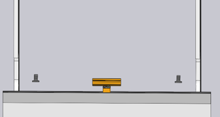
Check the backgauge limits by dragging to the left and right extents as shown below.
-
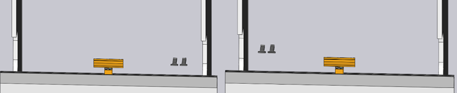
Also, drag and make sure that bgs don’t cross each other and the gap between them is maintained as shown below.
-
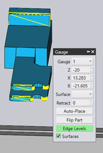
Check if the bg surfaces are shown correctly using the bg glob as shown below. Add MCAnalysis=1 in experimental.ini found in System folder of Flux installation. This enables the Surfaces checkbox to be available in bg glob.
DevNotes:
The Surfaces checkbox appear by default in developer mode. Refer BG surfaces angle measurement for BG surface angle measurements.
-
When Surfaces checkbox is enabled, origin of the bg will also be indicated (red dot) along with the bg surfaces.
-
For Trumpf machines, the origin should be at the ends as shown below.
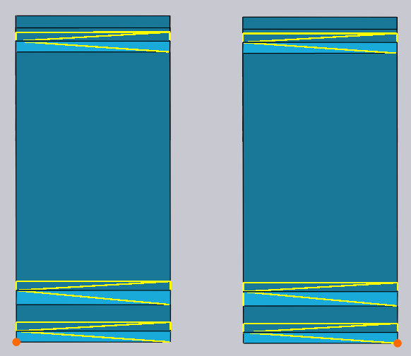
-
For JFY and Proteck machines, the origin should be at the center as shown below.
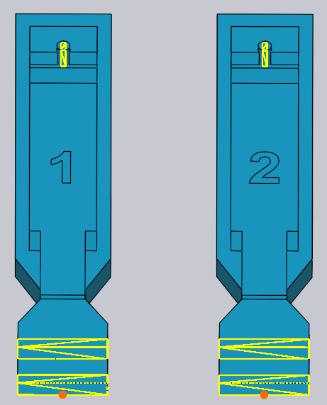
-
For some Proteck machines with crab finger bg, the origin should be lightly shifted from the center.
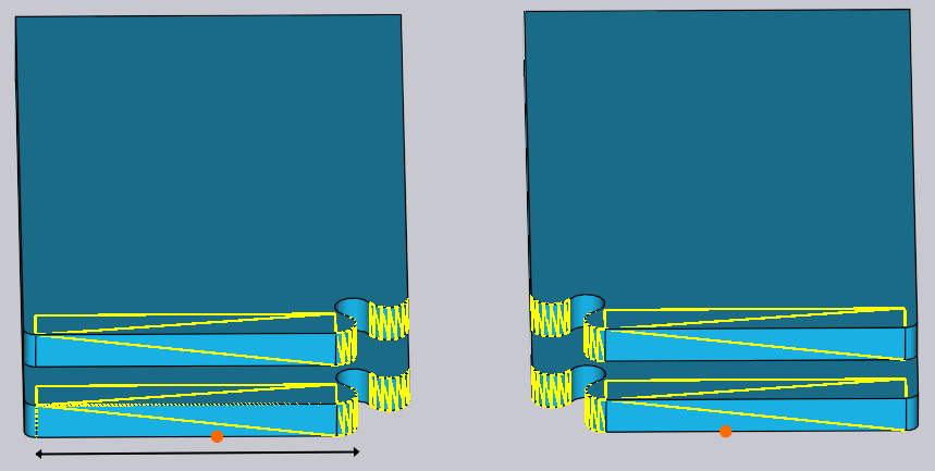
-
-
If bg limits/surfaces are wrong, check Back-gauge information and fix them.
-
If there are ACBLaserF, ACBLaserR and ACBLaserRail meshes for the machine, make sure that the ACBLaserRail is displayed only when ACB is activated for that machine. ACB can be activated for the machine through machine database dialog as shown below:
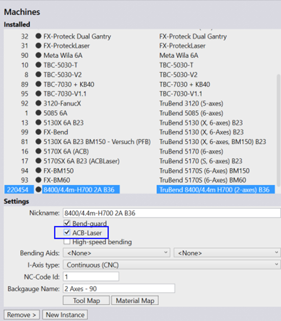
After activating ACB / LCB for the machine, verify if the ACB rail is displayed as shown below when Show die rail is on in the display. Verify if the sensors (which are in blue color on the ACB rail) are displayed only when Show ACB-Laser sensors is on in the display.
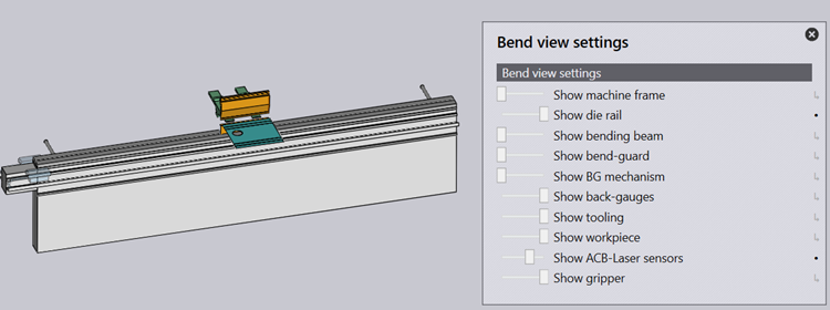
If the ACB is not activated, Show ACB-Laser sensors option won’t be part of the display dialog and ACB rail will not be displayed even if Show die rail is on.
-
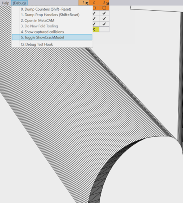
Run Flux.exe and click View menu and use Toggle ShowCrashModel to check the triangle count of the machine model. Remember to set MCAnalysis=1 in experimental.ini for this option to appear in View menu. Refer the image below. This image has too many triangles which could have cleaned up properly.
DevNotes:
Toggle ShowCrashModel will be under Debug menu by default in developer mode.
-
If tooling and other layers are in place, check generation of NC code.
-
For JFY machines, the NCCode section should be as shown below:
[NCCode] Type=0 Extension=fx ControlType=RANoteBelow steps are relevant only for developers. -
Do flux.console UnStreamlineWad x:\data\archive\machines - this will unpack the folder using the redirect.map and effectively make a lot of duplicate copies. This means after that each machine folder in x:/data/archive/machines will be complete, and needs no redirection.
-
After validating machine import, copy machine id folder created in X:\Data\Machine folder to X:\Data\Archive\Machines.
-
Do flux.console StreamlineWad x:\data\archive\machines - this will find all duplicates and rebuild from scratch the redirect.map file.
-
Now check the model folder for the machine, which will have unique mesh/mesh2 files (see Creating mesh2 file for further reference). Open the mesh/mesh2 files into Flux and verify that the original source file name matches the original .3d files given.

-
Create a respective branch in ReFlux repository and add the original .3d models to the respective machine brand folder in Y:/Models and push these into git.
-
Updating manifest.txt:
-
Make entry for the new machine in manifest.txt in X:\Data\Archive with first three fields namely ID, NAME, NCNAME.
-
For JFY machines, in manifest.txt, the machine entry should be added by ordering first by machine length, followed by tonnage and then by crowning style (H followed by M).
-
4 axes machine should be placed before 6 axes
-
Run Flux.Console.exe UpdateBMCManifest which will update the remaining fields of the machine in manifest.txt.
-
-
Finally you will have modified redirect.map, manifest.txt and the machine id folder with the unique mesh files. Push these in the respective git branch.
Tandem machines
Tandem machines in Flux are structured into 5 machines: the left and right standalone machines, the tandem machine and the internal machines. The internal machines are basically the constituent machines of the tandem machine. These machines are not visible in the machine database of Flux.
Naming conventions
We are standardizing the naming conventions used in the machines to maintain consistency (see Case 38892). In line with this, use the format as seen below.
Name: 81250/8m-H1000/HD 6A TA-L B36
NC Name: TruBend 81250/8m H1000/HD (6-axes) TA-L B36
The constituent machines will have to include the 'internal' tag as seen below. Ensure they are included in the bmachine.ini before importing the machines.
Name: 81250/8m-H1000/HD 6A TA-L (Internal)
EPost Inclusion
If the WIBU used is not yet included in Flux, a license error is thrown. So, please ensure that the EPost value is updated in Flux before running this.
Importing machines
-
First import the left and right standalone machines following the same steps until NC code generation.
-
Similarly, import the left and right internal machines. Add 'TandemID=(rightID + 1)' to the 'Extra' section of both the left and right machine.curl files. If not, an error is thrown during tandem machine creation.
-
Once the standalone and constituent machines are imported, copy all the four machine folders to X:\Data\Archive\Machines.
-
Now, to import Tandem machine, run the following command, where leftID and rightID refer to the IDs of the internal machine.
Flux.Migrate MakeTandemMachine leftID rightID
-
Tandem machine folder (rightID + 1) will be created in X:\Data\Archive\Machines.
-
Do not create manifest entries for the constituent left and right machines.
-
Continue with UnStreamlineWad step.
-
Check the machine.curl to set the
ACBChainPosvalue for the tandem machine. This may not be accurately set through import. -
Check the display of ACB-Laser sensors and rail.
BG surfaces angle measurement
This section explains how to measure start angle and end angle for bgs that have crab finger surfaces.
|
Note
|
The start angle should be less than the end angle. |
Measuring angle1 for left back-gauge
-
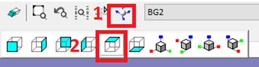
Open left back gauge file say BG1.3d in MetaCAM and click the Rotate View and select the view as highlighted in the image below:
-
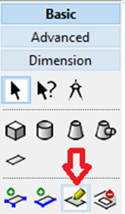
Click on the edit plane button in MetaCAM.
-
Press Shift key and click at the specified position shown with arrow in the image below:
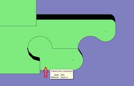
Sketch tab will open as shown in the image below:
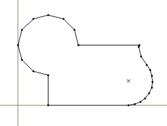
If not clicked correctly on the specified position, the orientation of the plane in the sketch tab will be incorrect.
-
Click the Line mode in MetaCAM
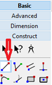
-
Draw three lines Center (1), Start (2) and End (3) from the center point as in the image below:
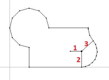
-
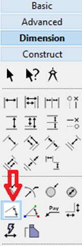
Select Dimension then click the Angular mode to measure the angles
-
Measure start angles by clicking line1 and line2 and end angle by clicking line1 and line3. The angle measurements will be as shown below:
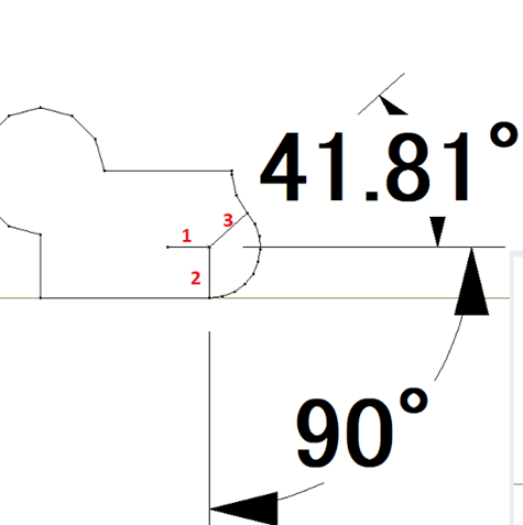
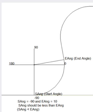
Consider the start angle1 value as negative, as these values are from -180 to 0. So, in this case the start angle1 of BG1 is -90. End angle1 values are from 0 to 180. So, in this case the end angle1 value is 41.81. See the below image for reference.
Measuring angle2 for left back-gauge
-
Repeat steps 1 & 2 in section Measuring angle1 for left back-gauge
-
Press Shift key and click at the specified position shown with arrow in the image below:
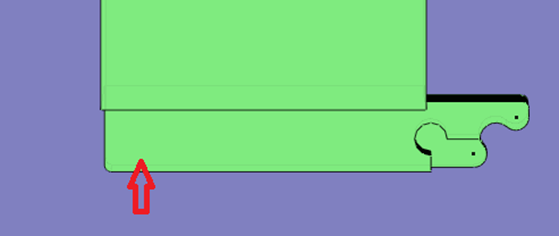
Sketch tab will open as shown in the image below:
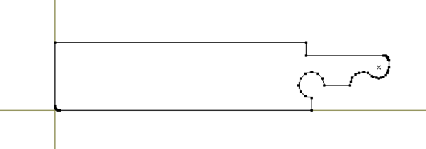
-
Click the Line mode in MetaCAM and draw three lines Center (1), Start (2) and End (3) from the center point as shown in the image below:
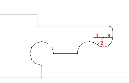
-
Select Dimension then click the Angular mode to measure the angles as said in previous section
-
Measure start angles by clicking line1 and line2 and end angle by clicking line1 and line3. The angle measurements will be as shown below:
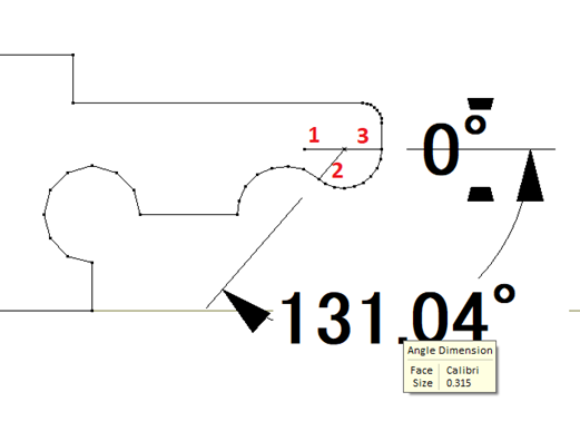
Consider the start angle2 value as negative as it ranges from -180 to 0. So, in this case start angle2 of BG1 is -131.01. And end angle2 ranges from 0 to 180. So, in this case the end angle2 values is 0. See image for reference.
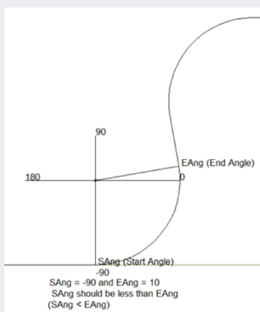
Measuring angle1 for right back-gauge
-
Open right back gauge file say BG2.3d and repeat steps 1 & 2 of section Measuring angle1 for left back-gauge
-
Press Shift key and click at the specified position shown with arrow in the image below:
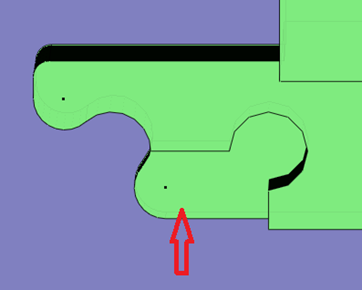
Sketch tab will open as shown in the image below:
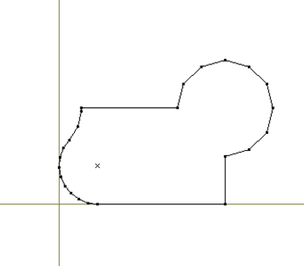
-
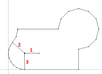
Using Line mode in MetaCAM and draw three lines Center (1), Start (2) and End (3) from the center point as shown in the image below:
-
Using Angular dimension mode, measure start angles by clicking line1 and line2 and end angle by clicking line1 and line3. The angle measurements will be as shown below:
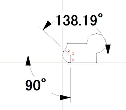
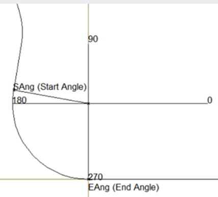
For right back gauges, start and end angle values range from 0 to 360. In this case, start angle1 is 138.19. See image below for reference and add 180 to the measured angle for end angle1, so end angle1 is 180 + 90 = 270.
Measuring angle2 for right back-gauge
-
Repeat steps 1 & 2 in section Measuring angle1 for right back-gauge
-
Press Shift key and click at the specified position shown with arrow in the image below:
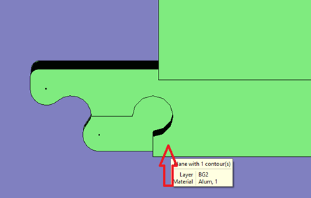
Sketch tab will open as shown in the image below:
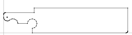
-
Using Line mode in MetaCAM and draw three lines Center (1), Start (2) and End (3) from the center point as shown in the image below:
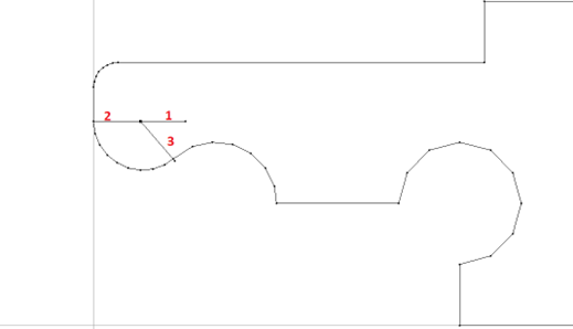
-
Using Angular dimension mode, measure start angles by clicking line1 and line2 and end angle by clicking line1 and line3. The angle measurements will be as shown below:
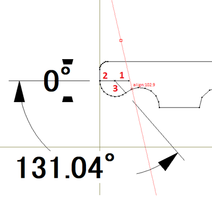
For right back gauges, the start and end angle values range from 0 to 360. Here start angle2 is 180. See image below for reference and add 180 to the measured angle for end angle2, so end angle2 is 180 + 131.04 = 311.04.