Importing bend tools
Usually zip file with bendtools.ini and dxf files for the tool system will be given. These files may require some changes and cleanup.
Here are the steps and checklist to be verified while importing bend tools into Flux:
-
Place these files in a folder say for eg UKB-Amada in Y:\BendTools.
-
Set ToolSystemID in the ini with the next available id in the manifest.txt in X:\Data\Archive\BendTools.
-
Use Flux.Migrate’s AuditBTools to verify and import these tools into Flux.
Usage: Flux.Migrate AuditBTools <toolSystemName>
where toolSystemName is like EHT, UKB-Amada etc.
-
After parsing the bendtools.ini if there are errors, AuditBTools will report.
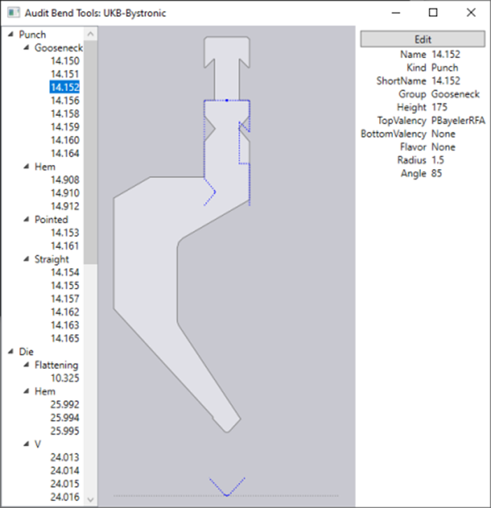
Once the errors are fixed, run the tool again to visually verify the tool profiles and the other parameters like angle, height etc. For eg if these values are not defined correctly the blue markers will not be in place as shown below:
-
Verify if top and bottom valencies are set properly using AuditBTools.
-
The profile drawings i.e., the plines in dxfs should be placed correctly at the required origin. Do NOT draw any point markers and remove the text entities in dxf.
-
There should be only single pline for most tools except wing dies and spring hem, only then 3d model can be rendered correctly in Flux.
-
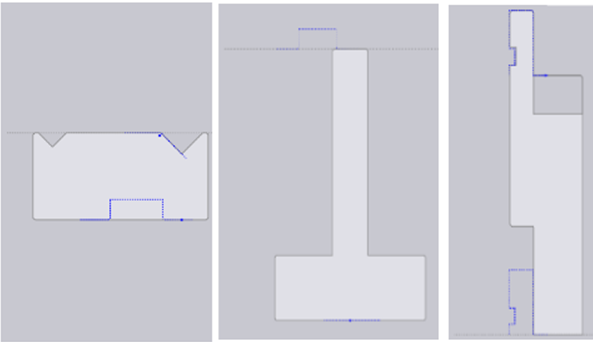
Below image shows some of the possible errors mentioned above
-
Name should not have _ instead use -.
-
MaxLoad for tools must be set in T/m in bendtools.ini, which will be displayed by Flux in KN/m.
-
Height of the tools can be decimals. It is important to make sure that the blue markers shown in AuditBTools for tools, both top and bottom, should match and align exactly.
-
Block tools should have angle as zero.
-
Tools with SplFlavor 3 and 5 must be grouped as Hem instead of FEV or Flattenning.
-
Wing dies should be grouped as Rollbend i.e., the shape field in the tool section must be set as Rollbend.
Ear dxfs
-
Check if the ear profile is set and relevant ear dxfs are provided for punches that have ear tooling.
-
Regarding ear drawings Flux needs a separate dxf file for ear profile.
-
For example, refer the ini data as shown below with a field EarProfile that refers to the corresponding ear dxf
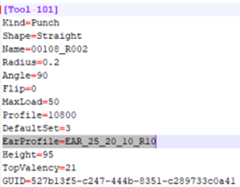
This way we can reuse the ear dxf if it is the same for other punches.
-
Only left ear profile is enough as shown below:
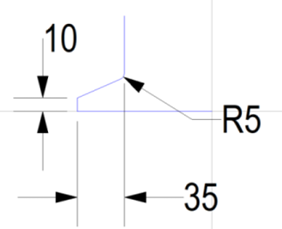
-
Sometimes the set defined might not have L100 or R100 pieces, but ear profile and drawing would have been provided. Check and rectify this.
Default set
-
Sometimes the set defined will have L100 and R100 but no ear dxf would have been provided and ear profile will also be missing in the respective Tool section.
-
For the tools where sets not found, use a relevant set defined in the bendtools.ini. Like if a punch has horn profile use a set which has L100, R100 etc and similarly for die use an already defined die set.
-
SetCount in [Sets] section must be correct. Like if there are 5 sets this SetCount should be 5. While adding or removing the sets make sure to set this properly. If this is not correct AuditBTools warns this as "Set not found".
Adapter / Extender / Holder concept
-
In general punch or die holders with same top and bottom valencies should be grouped as Extender.
-
Holders that have top and bottom valencies in the same tooling system for eg radius holder or blade holder etc. should be grouped as Holder
-
Holders that have either top / bottom valency of a different tooling system should be grouped as Adapter.
Radius inserts and holders
-
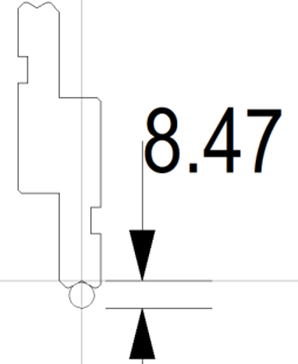
Draw the radius insert with the relevant holder as it is mounted in the machine as shown below.
Note how the the holder is placed at origin.
-
Remove the holder pline and save the radius insert dxf.
Only the insert pline, a little down from the origin will be the profile dxf for this insert.
-
Height of the radius insert is measured from the origin.
Set this height in bendtools.ini for these inserts.
-
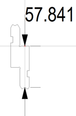
Height of the radius holders must be measured as shown below
Z-Bend Inserts
-
For Z-bend punch inserts, the SplFlavor is 101 and for Z-bend die inserts SplFlavor is 102.
-
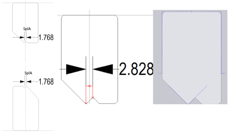
Flux requires angle and only SplA for these Z-bend inserts.
-
SplA is the horizontal distance between the peaks. Refer the image below:
Hem punches and dies
-
For hem punches below fields must be set
SplFlavor=2
SplA=-5
SplB=-12.8
SplC=58
-
Punch which does hemming without displacement are I0HemPunch and that require an additional field as set below:
I0HemPunch=1
-
AuditBtools shows the marker for SpI params of I0HemPunch. A green marker will be shown as in the image below:
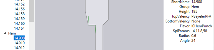
-
Refer the 'Bend Tool DXF Format' page under Appendix of Help.chm comes with Flux for the SplA,B,C values.
-
For the dies used with I0hemPunch, SplFlavor=5 must be set.
-
For dies as shown below set the die angle to 0 (because the two faces of the die are parallel) and set the V width to the width of the slot. Also, if there is a radius at the mouth of the slot, set that as the Radius parameter.
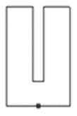
Spring loaded (feather hem) dies
-
For these dies, SplFlavor=3 must be set.
-
The ini fields SplA, SplB and SplD are required in this die’s [Tool n] section.
-
SplA is the Z-position for the part during hemming (the 'table' on which it rests)
-
SplB is the Spring Gap (travel distance of spring)
-
SplD is the Y-position for the part during hemming (how many mm in front of centerline). A +ve value means that it is to the front of the centerline and -ve value means that it is to the back of the centerline.
Note: MetaCAM SplC is SplD for Flux.Migrate as the old bendtools.ini in the repo have been like that. So please be sure to check and set these carefully.
-
Image below shows a spring hem die with +ve SplD value. Red line in the image is the centerline.
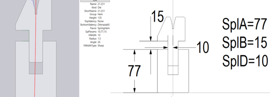
-
Green marker is shown in auditbtools for the special params defined as shown in the image above.
-
Image below shows a spring hem die with -ve SplD value. Red line in the image is the centerline.
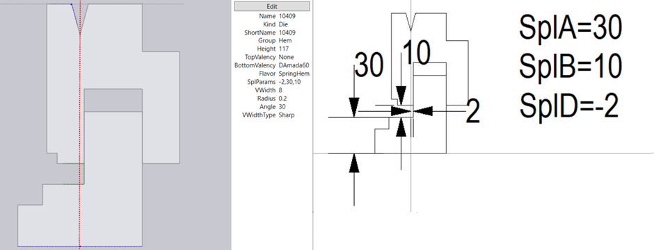
-
Refer the profile drawing below
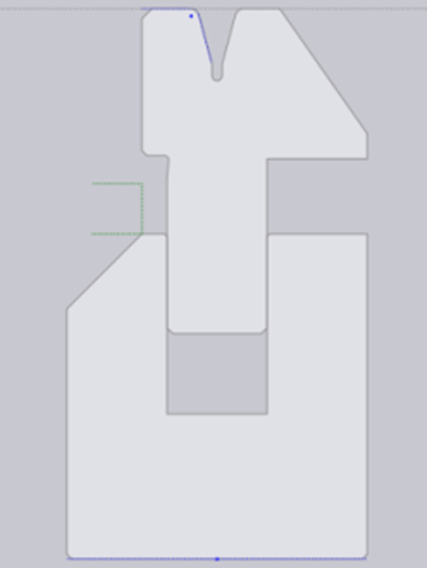
Seems the params are not correct and the profile orientation. The green marker should be aligned with the flattening notch for these tools.
-
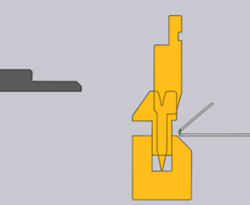
In the profile above, plines must be flipped in dxf otherwise the wrong side will be used for flattening as shown below
Wing dies
-
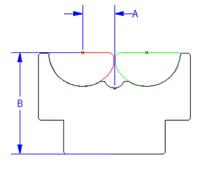
For these dies, SplFlavor=4 must be set. Also it requires SplA and SplB
-
SplA is the horizontal distance from the centerline of the die to the center-point of rotation of one of the wings. This is shown as A in the picture above.
-
SplB is the vertical distance from the bottom of the die to the center-point of rotation of the wings. This is shown as B in the picture above.
-
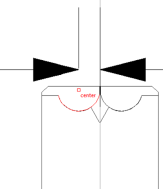
SplA can be measured in MetaCAM as shown below. Measure from the center of the arc of the wing to the center line of the die.