
Creating fold tool .tdata file
This document explains how to create fold tools like blank-holders, blades etc for Flux using a .tdata file. TDATA file is just a ZIP file. It contains an INI with some basic information, and a collection of drawings.
Structure of the INI file
The starting point for creating a fold tool is a data.ini file. This file is read first. This has only one section namely [Data]. The Data section provides the class (what type of tdata this is, like blade or blank-holder) and the name. It is important to set the name.
Upper blank-holder tdata
Here’s an annotated example for data.ini for upper blank-holder:
[Data]
Class=Fold-UBH     ; this specifies the type of tool. It is always Fold-UBH for upper blank-holder
Name=BH-2614099    ; name of the blank-holder
Setback=64         ; this is the distance shown in the figure below this ini section
                   ; It is normally 64 mm for a standard blank-holder, but could be more in the
                   ; case of a 'custom notched' blank-holder as seen in the image below
ReducedSet=1       ; Usually it is zero. If a couple of the 160mm pieces are missing, leading to a
                   ; total length of just 2803, rather than 3123 then this is set to 1.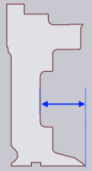
Geometry Conventions
Most of the blank-holder segments are extruded shapes mainly the profile and crash shapes. The other DXFs provide front and side views of the fixed and moving parts of the horn-type blank-holders.
The below listed dxf files are the geometry required for blank-holder.
* profile.dxf             ; side-profile of the tool
* crash.dxf               ; simplified collision drawing of the above
* lfixed.dxf              ; left horn fixed part with side and front profiles
* lfixedcrash.dxf         ; simplified collision drawing of the above
* lmoving.dxf             ; left horn moving part with side and front profiles
* lmovingcrash.dxf        ; simplified collision drawing of the above
* rfixed.dxf              ; right horn fixed part with side and front profiles
* rfixedcrash.dxf         ; simplified collision drawing of the above
* rmoving.dxf             ; right horn moving part with side and front profiles
* rmovingcrash.dxf        ; simplified collision drawing of the above
Here are some notes on the origin points:
-
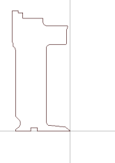
profile.dxf - This is the side profile of the tool. Please note the orientation, and note that the reference point of bending should be at 0,0. The profile.dxf file must contain just one POLYLINE, no other entities. Refer the image below:
-
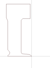
crash.dxf - The crash.dxf is the simplified version of profile.dxf used in collision checking. It is important that there are NO CURVES in this polyline, they must be approximated using straight lines. Don’t use too many straight lines or the collision check will be too slow. Use the standard files as examples, and try to approximate each arc with a tolerance of up to 0.5 mm or so.
-
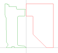
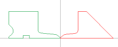
lfixed.dxf - A pair of profiles providing the front and side view of the fixed piece of the left (L199 piece). Note that these profiles must be drawn in the SIDE and FRONT layers of the DXF file. Also, note that the side view has bottom right corner at 0,0 and the front view has bottom left corner at 0,0. The two views must have exactly the same height, otherwise Flux will not be able to convert these two view into a single 3D model. Left horn fixed drawings with side and front profiles are as shown below:
-
lfixedcrash.dxf - A simplified version of lfixed.dxf that is used for collision checking. As with all the crash DXF files, this simplified version should have two polylines with NO CURVES.
-
lmoving.dxf - Front and side views of the moving part of the L199 piece
-
lmovingcrash.dxf - Simplified collision drawing of the above
-
rfixed.dxf, rfixedcrash.dxf - Visualization drawing and collision drawing of the right side fixed piece (R199)
-
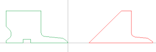
rmoving.dxf, rmovingcrash.dxf - Visualization drawing and collision drawing of the right side moving piece. Note that the front view has it’s bottom right corner at 199,0.
Lower blank-holder tdata
Here’s an annotated example for data.ini for lower blank-holder:
[Data]
Class=Fold-LBH     ; this is the type of tool. It is always Fold-LBH for lower blank-holder
Name=LBH-135       ; name of the blank-holder
Geometry Conventions
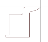
Lower blank-holder segments are extruded shapes that have only the profile and crash shapes. This requires only two dxfs, profile.dxf and crash.dxf similar to upper blank-holder and that the reference point of bending should be at 0,0.
Refer the image below for profile.dxf:
Uppder / lower blade tdata
Here’s an annotated example for data.ini for upper / lower blade:
[Data]
Class=Fold-UBW            ; this is the type of tool. It is always Fold-OBW for upper and Fold-UBW lower blade
Name=LI-135               ; name of the blank-holder
MaxAngle=135              ; maximum angle we can bend in one step (in radians)
Tonnage=150000            ; maximum tonnage for this blade, in N/m
Geometry Conventions
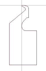
Upper / lower blades requires three dxfs, profile.dxf and crash.dxf similar to upper blank-holder, and also a locus.dxf that gives the swept profile.
Refer the image below for lower blade profile.dxf:
locus.dxf for lower blade as shown below:
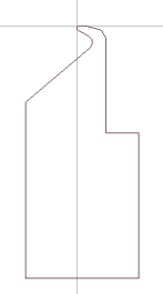
Refer the image below for upper blade profile.dxf:
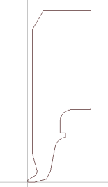
locus.dxf for upper blade as shown below:
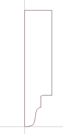
Importing a .tdata into Flux
Once you have modified the required drawings, save the updated files into a ZIPFile and rename it like BH-XYZ.tdata, where the XYZ must match the name specified inside the data.ini file.
Here is the required naming convention for the tools:
Upper blandk-holder - BH-XYZ.tdata
Lower blandk-holder - LBH-XYZ.tdata
Upper blade         - OBW-XYZ.tdata
Lower blade         - UBW-XYZ.tdata
Then, this can be imported into Flux and used for a machine.